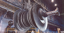

Despite their complexity, steam turbine blades and rotor develop cracks for a handful of reasons at multiple locations (airfoil, root, tenon, snubber, cover band, disk rim etc). To recommend a permanent fix first requires an understanding of how and why unexpected fatigue or rupture occurred. Our analysis can help operators to make the right decisions.
STEAM TURBINE
Vibration (high cycle fatigue)
Synchronous vibration:
When the at-speed natural frequency of a bladed-disk system matches the whole numbers of rotating frequency, the synchronous vibration may occur due to the existence of appreciable stimulus of per rev excitation.
Non-synchronous vibration:
How it happens: The stimulus normally comes from unstable flow and is unrelated to rotating speed. If the frequency of stimulus matches the at-speed natural frequency, the vibration may occur. It is referred as non-synchronous vibration to differentiate it from synchronous vibration. Nowadays, non-synchronous vibration has become more prominent due to many units are run at partial loads or as part of combined cycle which could increase magnitude of unstable flow.
Solutions:
-
Detuning the bladed-disk natural frequency to avoid resonance.
-
Adding additional damping elements to suppress vibration.
-
Reducing stimulus from unsteady flow.
-
Re-profiling local geometry to reduce stresses.
-
Interpreting BVM data and tracking accumulated high cycle fatigue (HCF) damage.
Case studies:
Creep
Many components of the turbine are subjected to appreciable stresses while operating at high temperatures. These parts will experience creep deformation and stress relaxation under the combination of unfavorable stress and temperature conditions. Creep rupture may occur as a result of long-term exposure to moderate level of stresses that are well below the yield strength of the material if the component is subjected to high temperatures.
For steam turbines, the most vulnerable rows to creep damage are HP and reheat IP stages where both mechanical stresses and temperatures are relatively high. Creep deformation or damage has been mostly observed in the blade root and tenon/cover areas.
Solutions:
The current practical approach is to reduce mechanical stress at critical locations by adjusting blade profile to reduce mass, changing local geometry or using lighter material of coverband.
Case studies:
Erosion
Steam turbine blades are distinctly subjected to water droplet erosion (WDE) caused by high energy impingement of liquid water droplets under high speed rotation. The last couple of stages of steam turbines are the most vulnerable to WDE.
WDE may become more prominent if units are running at partial loads or as part of combined cycle operation. Severe erosion damage may occur at the lower portion of the airfoil trailing edge as a result of reverse flow under part load operation. WDE is a complicated multiple phase steam flow phenomenon which requires an advanced computational fluid dynamics (CFD) analysis.
Solutions:
-
Stellite shield.
-
Repair by grinding off damaged area.
-
Risk assessment of existing cracks (crack propagation life study).
-
Identifying the limit for partial load operation.
Case studies:
Low cycle fatigue
Failures of low cycle fatigue (LCF) typically occur as a result of significant level and low number of reversals of stress. For the components repeatedly subjected to stresses beyond the yield strength of material, plastic deformation will occur/accumulate and cracks might initiate in a finite number of cycles.
For steam turbines, steady stresses are the primary driving force for LCF damage that is accumulated from loading and unloading experienced by the blade/disk at each completed speed cycle of the rotor. LCF can become a serious concern for the last stage (L-0) blade when the machine is operated in a cyclic fashion.
Casing is another component which might be vulnerable to LCF with repeatedly thermal cycling. Excessive thermal stresses due to pronounced temperature gradient could occur during transient operations and cracks may develop in a limited number of cycles.
Solutions:
-
Re-design of the profile at critical locations (e.g. inlet bowl area) to reduce stress magnitude and optimize stress distribution.
-
Repair by grinding off existing cracks and assessment of crack initiation and propagation life after repair.
-
Risk assessment of existing cracks (crack propagation life study) by leaving the damaged part as is till next outage.
Case studies:
Stress Corrosion Cracking
Stress corrosion cracking (SCC) is the formation and growth of cracks in a corrosive environment. It can lead to unexpected sudden failure of normally ductile metals subjected to a moderate tensile stress.
For steam turbines, SCC typically occurs in the dovetails in the wilson-line disks. More recently, SCC was also identified in the blade airfoil, particularly when the machine runs load following in a combined cycle unit. The rate of SCC growth is greatly influenced by the yield strength of alloy and operating temperature.
Solutions:
-
Repair by grinding off damaged area.
-
Risk assessment of existing cracks (crack propagation life study) by leaving the damaged part as is till next outage.
Case studies:

