

Compressor fatigue problems are often stage-specific. At the inlet, cracks form from corrosion or erosion assisted fatigue caused by non-synchronous vibration due to rotating stall and clashing. At the exhaust stages, transient thermal stresses accelerate the formation of cracks and reduce the cycling life of the rotor.
COMPRESSOR
Normally a multiple stage computational fluid dynamics (CFD) simulation is first performed to obtain pressure and temperature distributions throughout the compressor system. The results are then used as the boundary conditions in the subsequent single stage fluid and structural analyses.
Services for design evaluation of compressor components include performance audit, modal and dynamic response analysis, prediction of fatigue and remaining life and assessment of repair limit and damage tolerance.


-
At the inlet, cracks form from corrosion or erosion assisted fatigue caused by non-synchronous vibration due to rotating stall and clashing.
-
In exhaust stages, analysis is used to identify the transient thermal stresses which often occur at the rim attachments. Crack growth is analyzed using fracture mechanics to assist operators monitor fatigue crack propagation and plan rotor maintenance by identifying the number of cycles (starts, hot restarts) before critical crack size is reached.
-
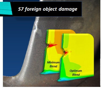
The advisability of FOD repairs to limit unit downtime are based on the impact they may have on both frequencies and stresses. Damage tolerance limits are specified for parts operated in the first few rows, which are most susceptible to corrosion or erosion. Tip displacements obtained by BVM sensors may be used with the FEM to establish fatigue life consumption attributed to rotating stall or clashing.